Assembling Guide for ptSolar Tracker
Introduction
The ptSolar APRS tracker from Custom Digital Services is a compact and energy-efficient device designed to send position and telemetry data via the Automatic Packet Reporting System (APRS). The system is powered by two solar panels. This guide walks you through every stage of assembling, testing, and deploying your ptSolar APRS tracker.
Whether you’re a seasoned amateur radio operator or an enthusiastic maker, this manual will support you in building a reliable and robust tracking device.
Tools and Materials Required
- ptSolar APRS Tracker Kit (PCB assembly, radio module, solar panels, super cap, programming/configuration headers, antenna wires, 3D printed carrier)
- Soldering iron and solder
- Wire cutters
- Needle nose pliers
- Protective eyewear (recommended)
- 5V TTL programming cable, such as the one sold from Custom Digital Services.
- Windows 10 or 11 PC
- ptConfigurator software, downloadable from www.ProjectTraveler.org
Unpacking and Inspecting the Kit
- Lay out all the parts from your ptSolar APRS tracker module kit on a clean, static-free work surface.
- Use the included bill of materials to verify every component is present. Check for damage from shipping.
- If any components are missing or damaged, contact Custom Digital Services before proceeding.
Assembling the Main PCB
Preheat your soldering iron to 350°C (or as recommended for your solder type). Follow the following instructions in order for best results.
Radio Module
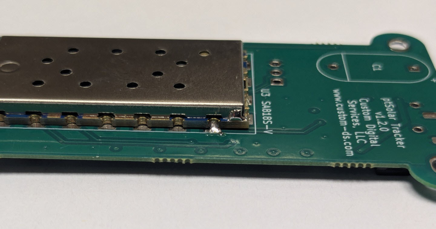
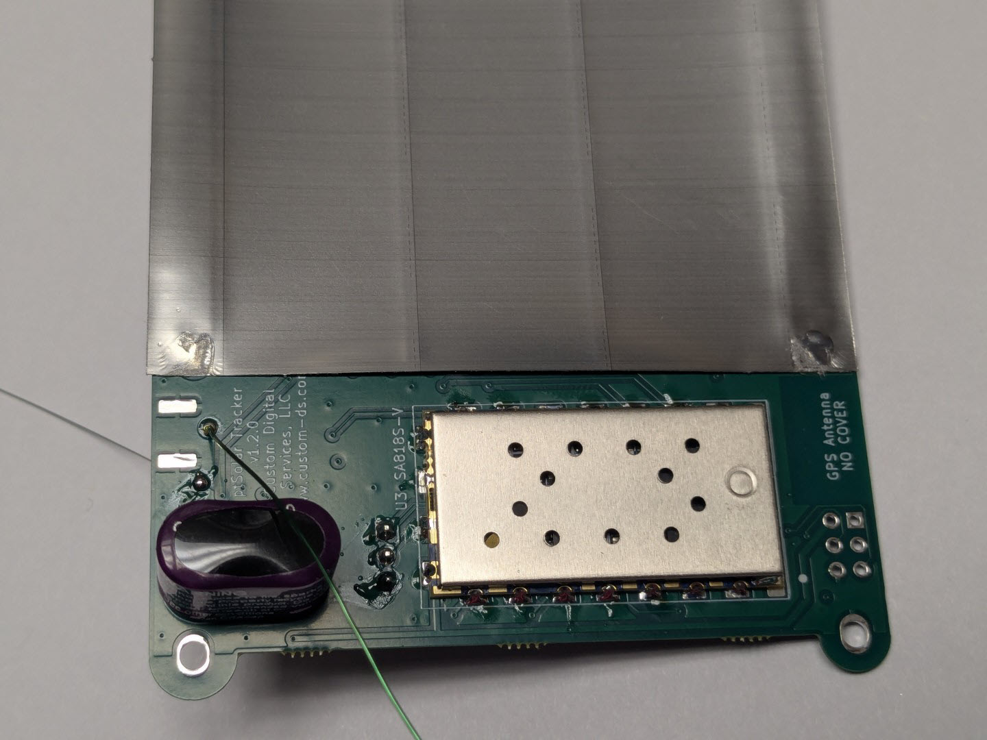
The SA818V module is soldered to the back side of the PCB assembly. Pay careful attention to the direction of the module. The large pad in the middle of the module goes towards the top of the PCB board, and the two long strips go towards the bottom of the PCB.
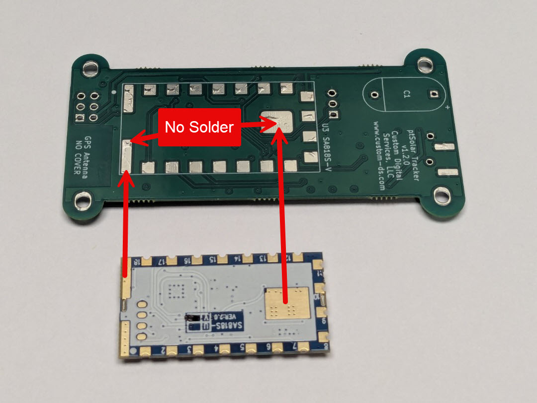
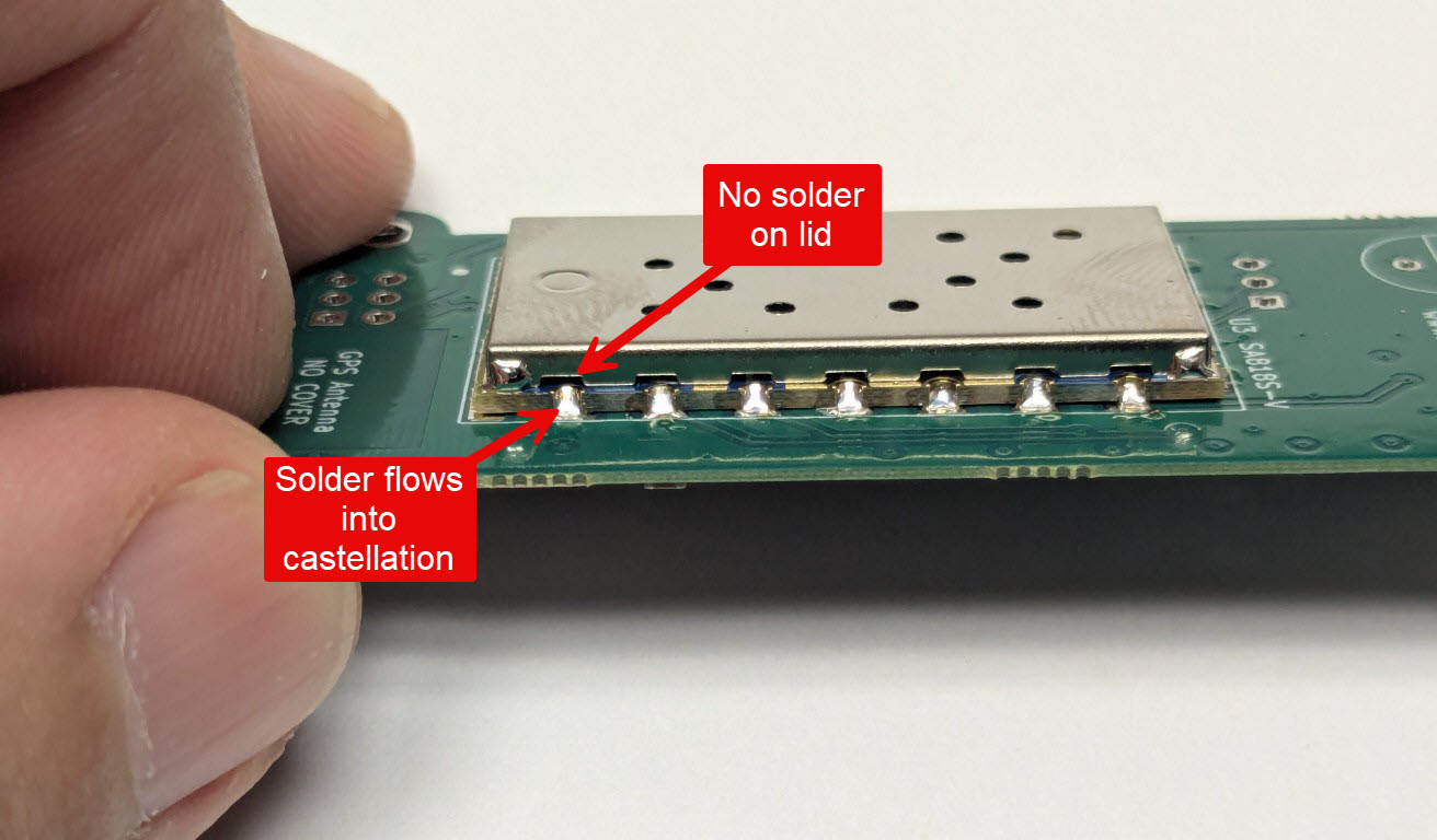
There is no need to solder the pad in the middle of the module, nor the two long strips at the bottom of the module.
Place the module on the PCB and carefully tack-solder one of the castellated pads along one side of the module.
Important: Before continuing, examine the position of the module along all four edges to ensure that it is properly centered. If it isn’t, this is the opportunity to reheat the single pad now and reposition it. Removal of the SA818V module after it is mostly soldered is very difficult and will likely cause permanent damage to the module and/or the PCB.
Inspect each pad to ensure that solder flowed nicely between the PCB and the edge of the castellation. Be sure that the solder did not extend past the castellation and onto the metal lid.
Programming Header(s)
Before operation, the ptSolar will need to be configured with your callsign and any specific flight parameters desired. The J2 header is used to configure these details once the board is completely assembled.
Install the 1x3 header J2 into the holes near the middle of the PCB. The pins should be installed on the side with all of the SMD components.
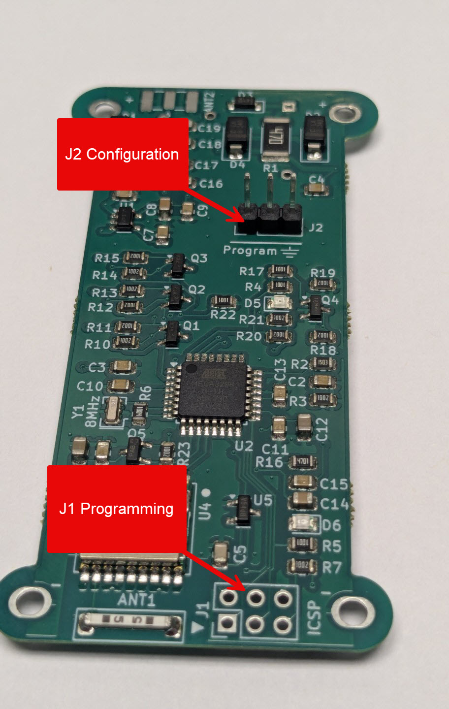
There is a second 6-pin header near the bottom of the board labeled J1. This header is optional and will save a small amount of flight weight by leaving it off. This header is used if you wish to upgrade the firmware that is operating on the ptSolar, and is not required for normal operation.
Super Cap
The solar panels provide power to the ptSolar, however the current produced is not sufficient to handle the high draw of the transmitter module.
A super cap is installed on the bottom side (where the transmitter module was installed). Be sure to look for the stripe running down one side of the super cap to indicate the negative terminal. The negative side should be towards the bottom of the PCB.
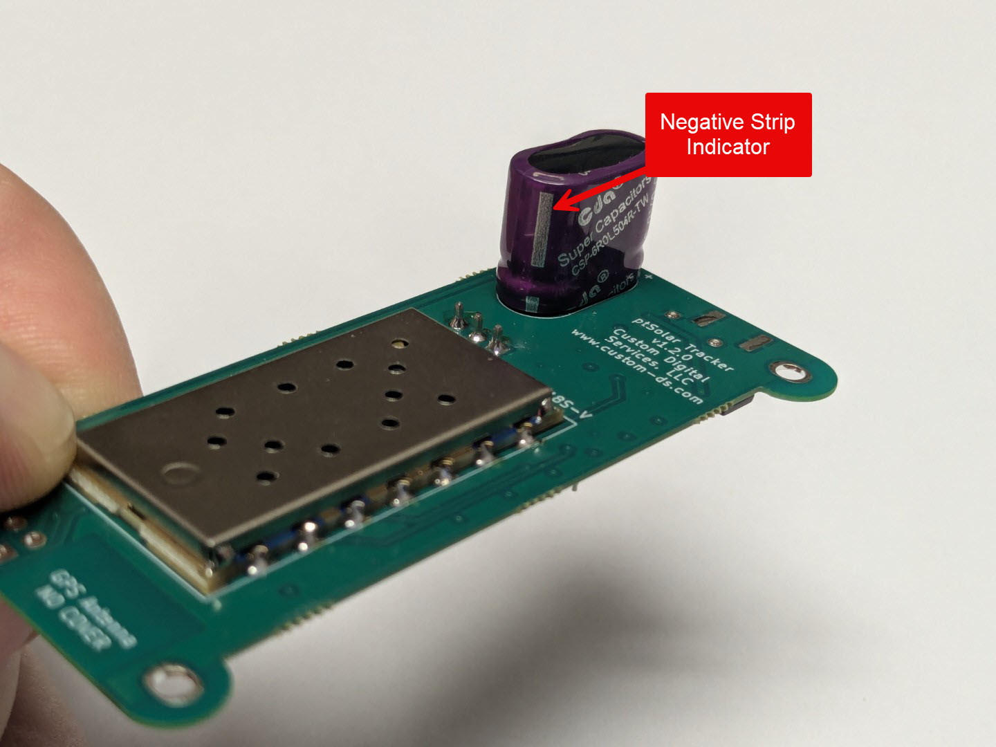
Trim the excess leads off of the capacitor once it’s soldered into position.
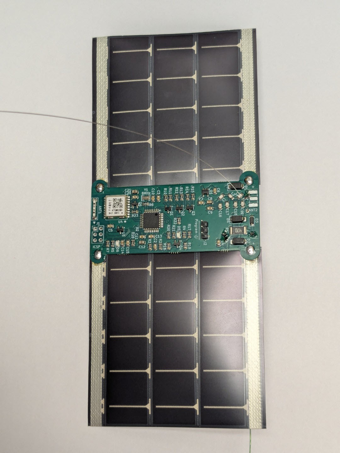
Solar Panels
Two flexible solar panels power the ptSolar tracker. The panels can be soldered to directly, however they have a thin waxy film over the conductive surfaces that needs to be removed prior to attaching to the PCB. The simplest approach is to simply melt it off with the solder.
The panels are polarized, meaning that there’s a positive and negative side to each panel, and you need to ensure that you have both panels aligned. The markings across the face of the panel indicate which side is which.
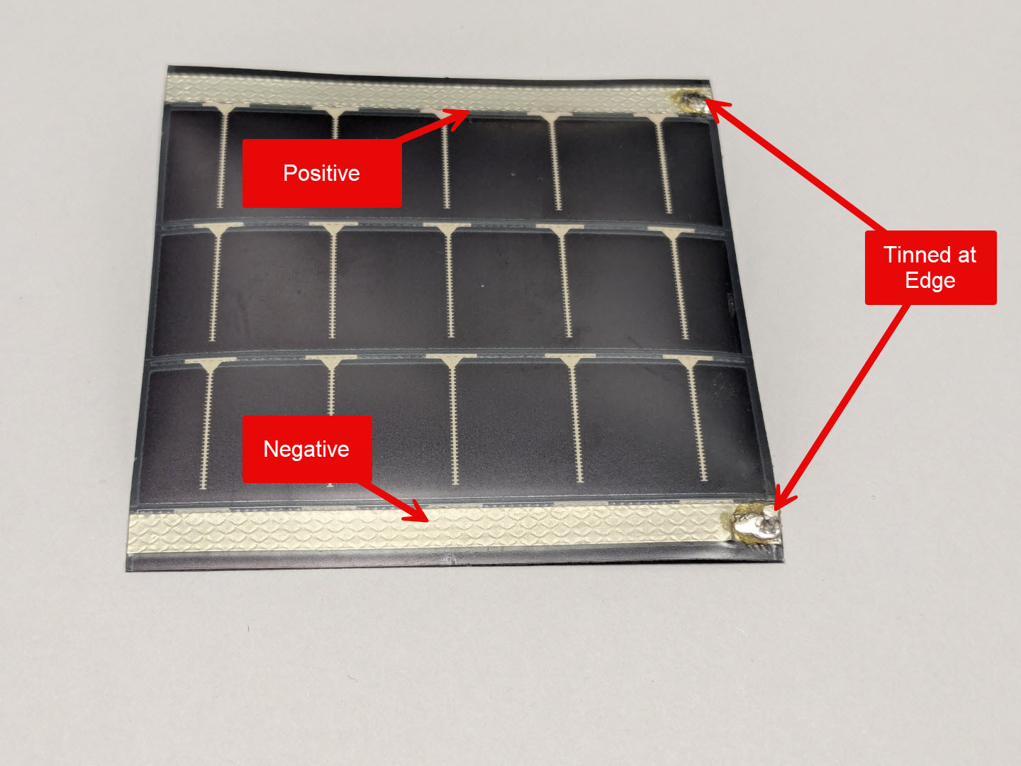
A right side and left side panel needs to be prepared by tinning the solder points. Just be sure to tin the opposite sides on the two panels. As you tin the panel by melting a blob of solder, the waxy film will melt away.
Place the first solar panel down on a heat-tolerant surface such as a scrap of wood. Lay the ptSolar PCB over the edge of the panel, with the PCB overlapping the black part of the panel by a millimeter or two.
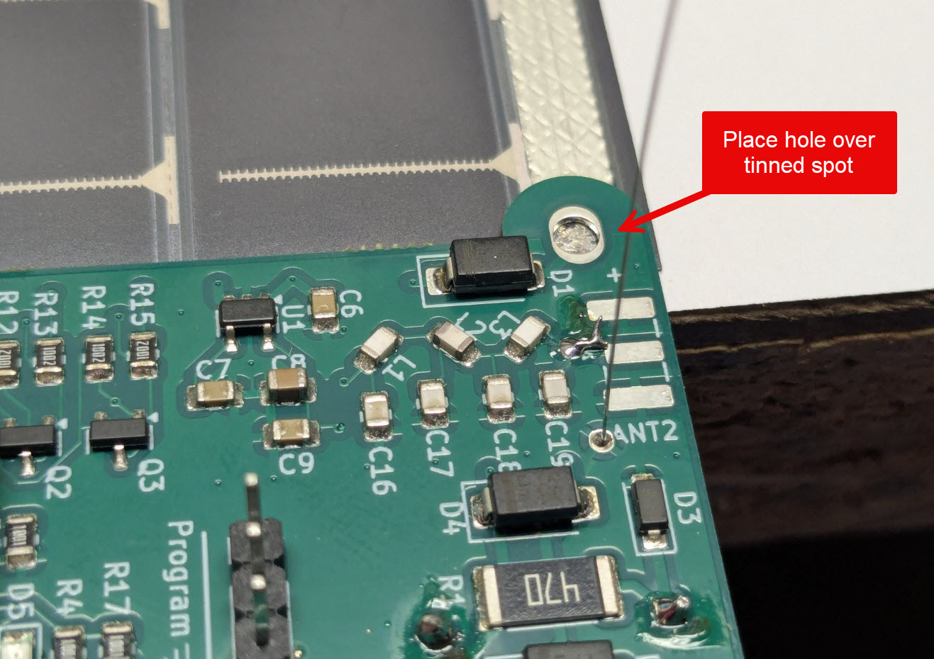
Place the soldering iron over the tinned area of the solar panel to reheat that solder, adhering it to the PCB. If necessary, add a small amount of fresh solder.
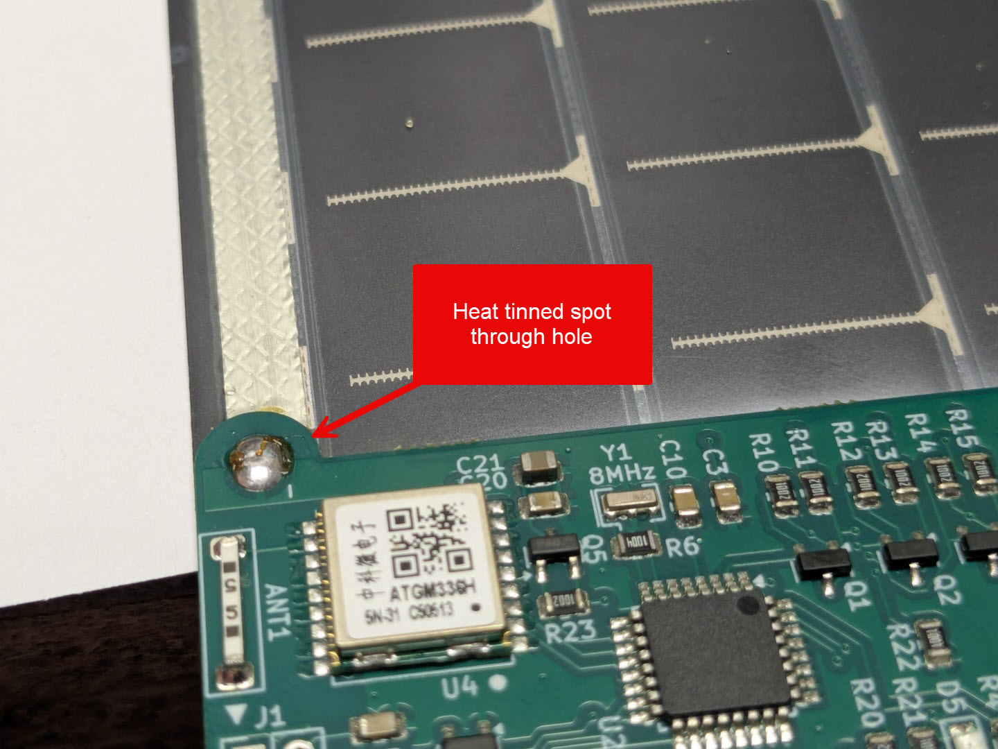
Repeat the process on the other side of the PCB, being sure to solder to the opposite side of the second solar panel.
Antenna
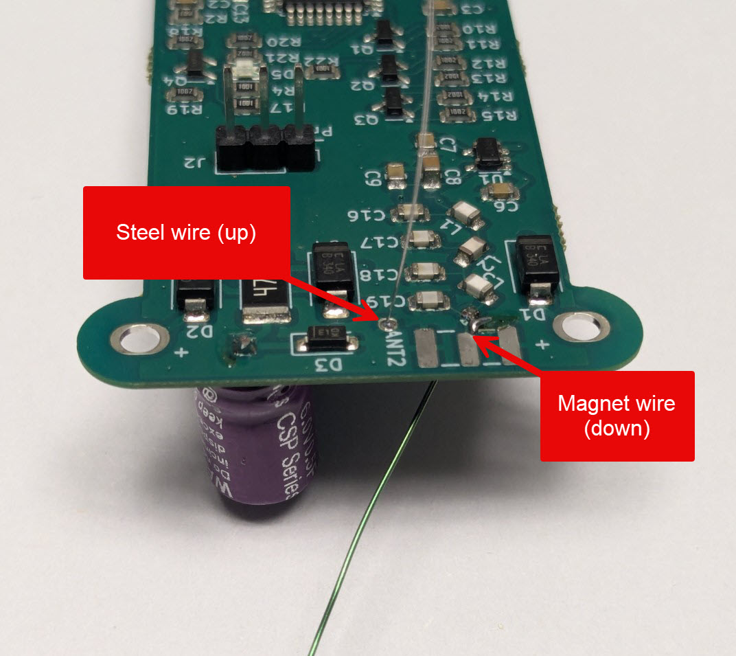
The tracker transmits on the 2m amateur band using a wire dipole. Two pieces of wire are included in the Kit – a stiff steel wire that will stand up semi-vertically, and a piece of magnet wire that will hang down below the tracker.
Prep the stiff, steel wire by first bending a small safety loop on one end of the wire. This helps prevent accidental poke to the eye, as the wire can be hard to see when you’re working with the tracker.
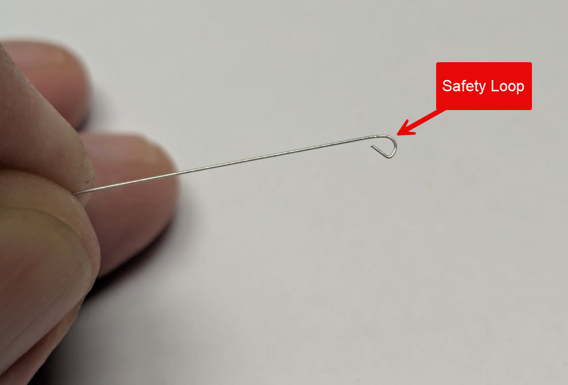
On the opposite side of the wire, bend a very short 90 degree bend in the wire, no more than 2mm in length.
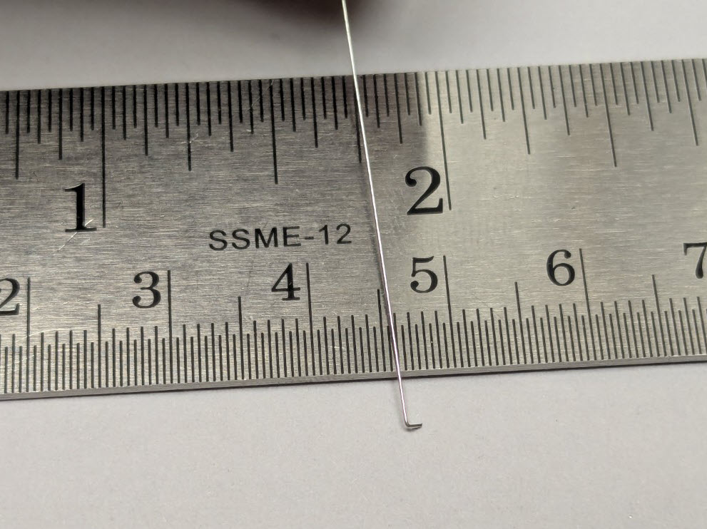
There are two remaining holes near the top edge of the PCB for the antenna wires. Insert the steel wire through hole closest to the label “ANT2”. The 90 degree bend on the end of the wire should be flush against the bottom of the PCB. Solder the steel wire into the hole, ensuring that the wire is pointed directly up from the top face of the board.
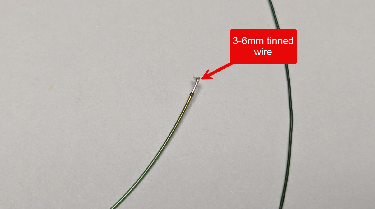
The second flexible wire has a thin enamel coating on it that can be melted off by tinning the end of the wire with a small amount of solder. You will see the coating bubbling off in a dark color, leaving a shiny tinned wire, approximately 3-5mm in length.
Insert the wire through the second hole, just of the left of the first hole, with the wire trailing down below the tracker.
Configuring the ptSolar
Review all of the soldering connections to ensure that they are clean solder joints, and are not shorting out across multiple pads.
The ptSolar needs to be powered up in order to perform the final configuration of your callsign, and any other parameters. Note that this is different from flashing a firmware to the microcontroller, which is generally unnecessary for a purchased kit as the kits already have a default firmware applied.
Applying power to the ptSolar can be accomplished in several ways
- Taking the ptSolar outside in full sun at mid-day
- A 200 watt plant grow light
- Power applied through the J1 6-pin plug, such as with an Atmel ICSP programming cable
Download the ptConfigurator from the ProjectTraveler.org website. ptConfigurator is the software used to set the configuration values on a ptSolar tracker. It will download a .MSI file that can be installed on any Windows 10 or Windows 11 PC. Double-click the .MSI to install the software.
Plug the configuration cable (sold separately) into a USB port. Normally Windows will automatically install the appropriate driver, and create a serial port on the computer.
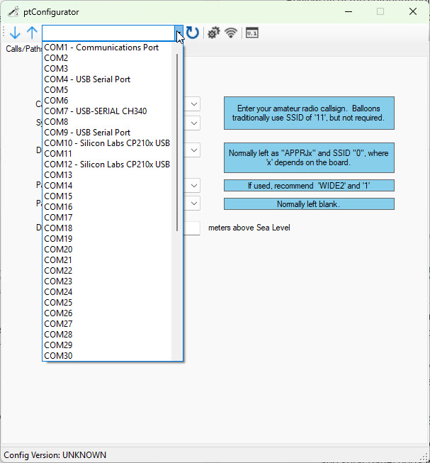
Open the ptConfigurator software on the PC. Across the top toolbar, select the COM serial port from the list od devices.
Helpful Tip: If you are unsure which serial port was created by the Configuration Cable, unplug the cable from the USB port. Click on the round Refresh button next to the list of serial ports. Drop the list of serial ports, making note of which ones have labels next to them such as “COM9 – USB Serial Port”.
Plug the Configuration Cable back into the PC and click the round Refresh button again, looking for a new COM port that previously did not have a label associated with it.
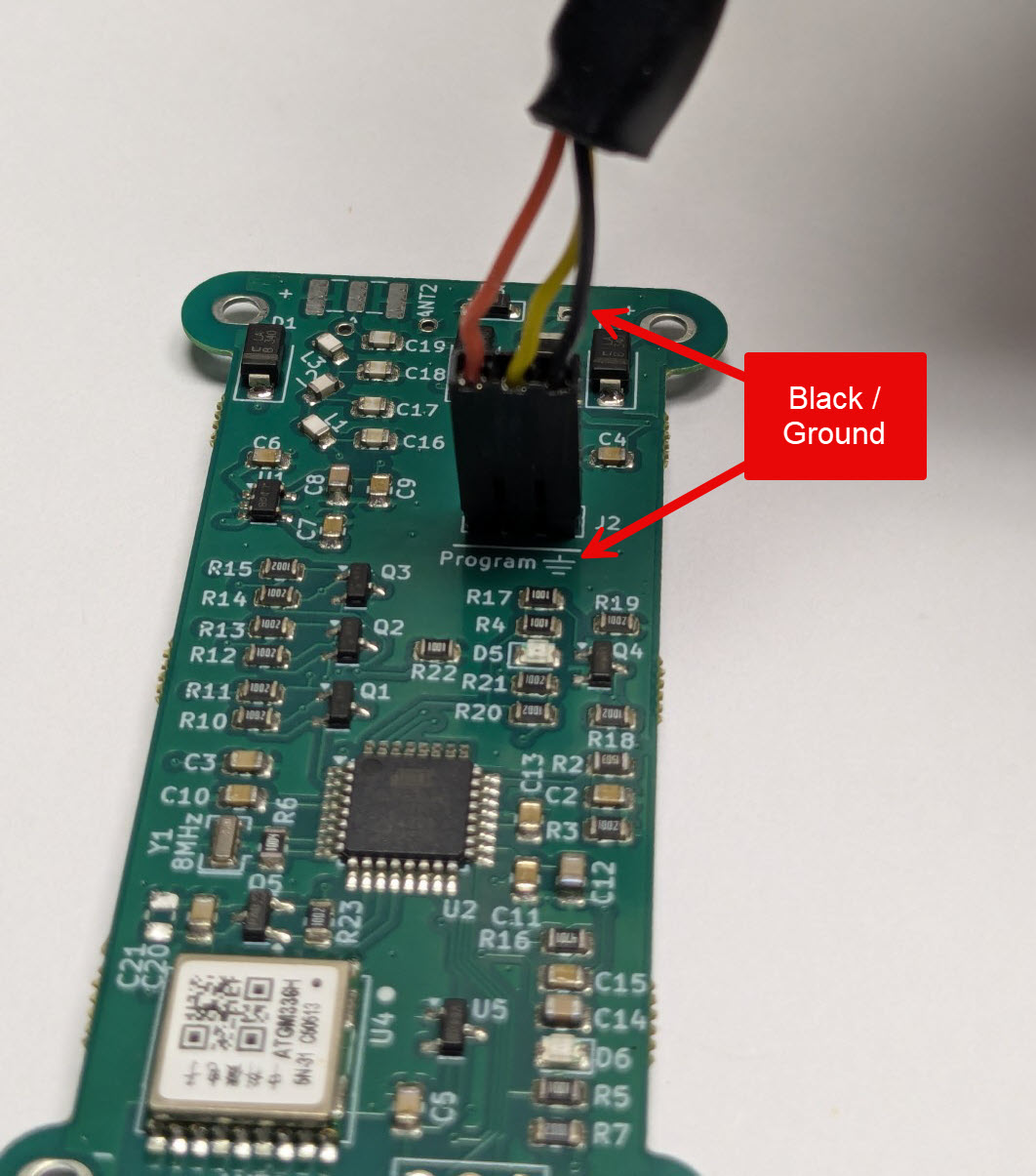
Plug the Configuration cable into the 3-pin J2 plug near the top of the PCB. Align the black ground wire with the ground symbol on the pin closest to the edge of the board.
Configuring the ptSolar
Apply power to the ptSolar tracker through one of the means listed above. If you are outdoors using the sun as your power source, note that it can take 15-60 seconds of full sun before the tracker powers up. You should see the green LED D6 flash as the microcontroller powers up.
Once the tracker is powered, click the Down Arrow button to download the currently running configuration from the Tracker into the ptConfiguration tool. You should see “Config Version: PT0101” at the bottom of the status bar in ptConfigurator. This is your indicator that the configuration was read from the ptSolar.
The most common settings for Pico Balloon tracking are:
Calls/Paths
- Callsign – Set the callsign with your ham radio callsign. If you wish to use an SSID, select it from the drop-down menu to the right of the Callsign field.
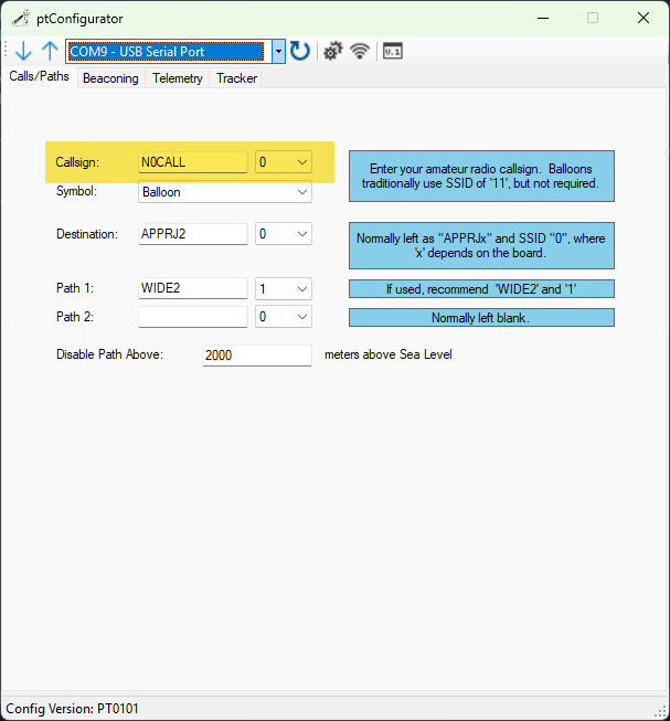
Beaconing
- Low Power Beaconing – This puts the tracker in the low power mode that is optimized for solar operation.
- Minimum delay between transmissions – This is how often it will transmit assuming it has sufficient solar power, and has a solid GPS lock. On the ground this time will often be longer than the value specified, however when the Pico balloon is at altitude, it will generally beacon at the fastest rate specified.
- GPS Voltage Enable Threshold – The voltage that the GPS becomes active. 3500mV is a safe value. Don’t adjust this unless you understand the ramifications of doing so.
- Transmit Voltage Enable Threshold – This voltage that the tracker waits to build up to before transmitting. 4100mV is a safe value. Don’t adjust this unless you understand the ramifications of doing so.
![]()
Telemetry
- Status Message – A free form area that transmits at the end of the packet. A shorter message will consume less power during the transmit cycle. Avoid using punctation unless you’re familiar with the APRS protocol.
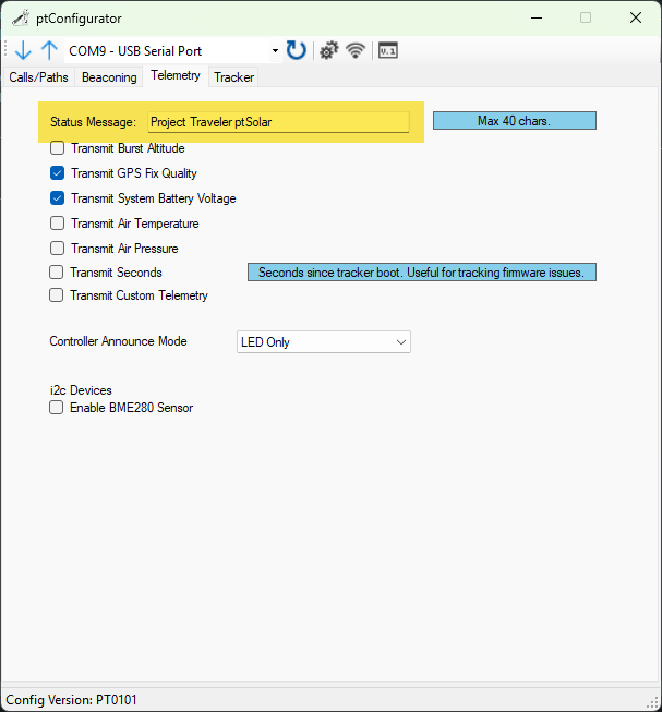
The other check-boxes can usually be left as default.
- Burst Altitude is irrelevant for a Pico (floater) balloon.
- GPS Fix Quality can be useful for watching the status of the GPS receiver.
- Battery Voltage can be useful for monitoring the output of the solar panels.
- The ptSolar does not contain air temperature or pressure sensors, and these options will not work on this tracker.
- Transmit Seconds will transmit the number of seconds since the tracker powered up. This can be useful if you are curious if the tracker is loosing power due to low solar output or another issue.
- Custom Telemtety is supported, but requires a custom firmware build. This is generally not used on a ptSolar.
- The Controller Announce Mode can be set to Off or LED Only. Turning the light off saves a very small amount of energy, but is not noticeable under normal circumstances.
- There is no BME280 sensor installed on the ptSolar tracker, and checking this box will not do anything.
Tracker
- Unless you want your tracker to stay on a specific frequency, check the box to Use Global Frequency Database. This will look up the region’s APRS frequency based on the current position.
- Powering down the GPS during transmission will help avoid the Super Cap from falling below unsafe levels during the APRS transmission.
- Delay Transmit until GPS Lock will delay the transmission past the number of seconds defined on the Beaconing page in order to wait for a valid GPS lock. This can be very useful in low power, and high RF-environments where the GPS may be struggling to get a solid lock.
![]()
Applying the Configuration
Once all four tabs of the ptConfigurator are configured as desired, press the Up Arrow. If the tracker is still powered on, it will upload the settings permanently into the EEPROM on the ptSolar.
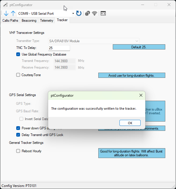
Always verify that the settings were properly applied. The best approach is to close out of ptConfigurator, then re-open it and re-select the COM port and click the Down Arrow to read in the configuration from the ptSolar. Your settings should re-appear inside of ptConfigurator.
It is also recommended to take the ptSolar outdoors where it can receive sufficient sunlight and a solid GPS lock, and verify the APRS reception using a local APRS receiver. Note that depending on your proximity to an iGate receiver, it is common for the ptSolar tracker to NOT be gated onto the Internet until it has attained a couple hundred meters of altitude.