Assembling Guide for ptFlex Tracker
Introduction
The ptFlex APRS tracker from Custom Digital Services is a compact and energy-efficient device designed to send position and telemetry data via the Automatic Packet Reporting System (APRS). The system is powered by a 2-cell LiPo lithium battery at 7.4V. This guide walks you through every stage of assembling, testing, and deploying your ptFlex APRS tracker.
Whether you’re a seasoned amateur radio operator or an enthusiastic maker, this manual will support you in building a reliable and robust tracking device.
Tools and Materials Required
- ptFlex APRS Tracker Kit (PCB assembly, radio module, programming/configuration headers, and battery cable)
- Soldering iron and solder
- Wire cutters
- Needle nose pliers
- Protective eyewear (recommended)
- 5V TTL programming cable, such as the one sold from Custom Digital Services.
- Windows 10 or 11 PC
- ptConfigurator software, downloadable from www.ProjectTraveler.org
Unpacking and Inspecting the Kit
- Lay out all the parts from your ptFlex APRS tracker module kit on a clean, static-free work surface.
- Use the included bill of materials to verify every component is present. Check for damage from shipping.
- If any components are missing or damaged, contact Custom Digital Services before proceeding.
Assembling the Main PCB
Preheat your soldering iron to 350°C (or as recommended for your solder type). Follow the following instructions in order for best results.
Radio Module
The SA818V module is soldered to the front side of the PCB assembly. Pay careful attention to the direction of the module. The large pad in the middle of the module goes towards the top of the PCB board, and the two long strips go towards the bottom of the PCB.
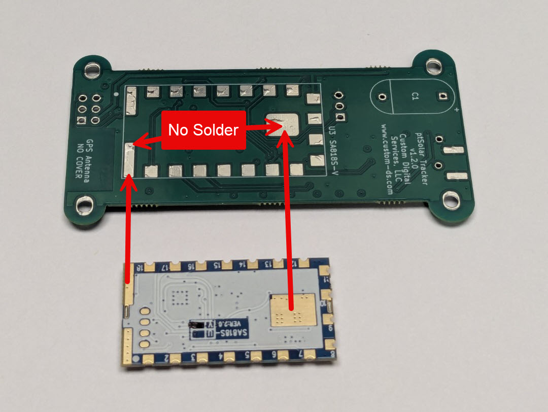
There is no need to solder the pad in the middle of the module, nor the two long strips at the bottom of the module.
Place the module on the PCB and carefully tack-solder one of the castellated pads along one side of the module.
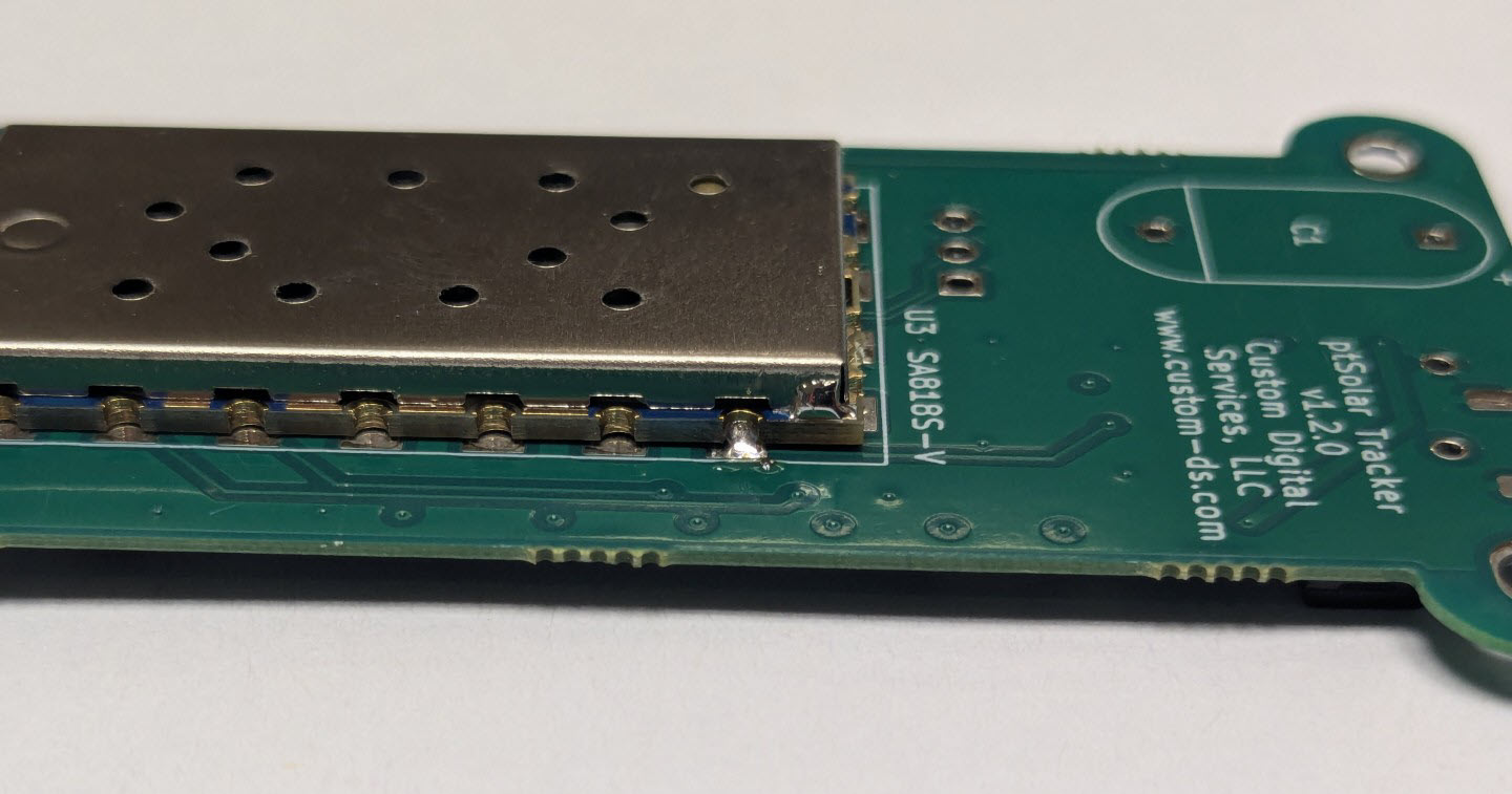
Important: Before continuing, examine the position of the module along all four edges to ensure that it is properly centered. If it isn’t, this is the opportunity to reheat the single pad now and reposition it. Removal of the SA818V module after it is mostly soldered is very difficult and will likely cause permanent damage to the module and/or the PCB.
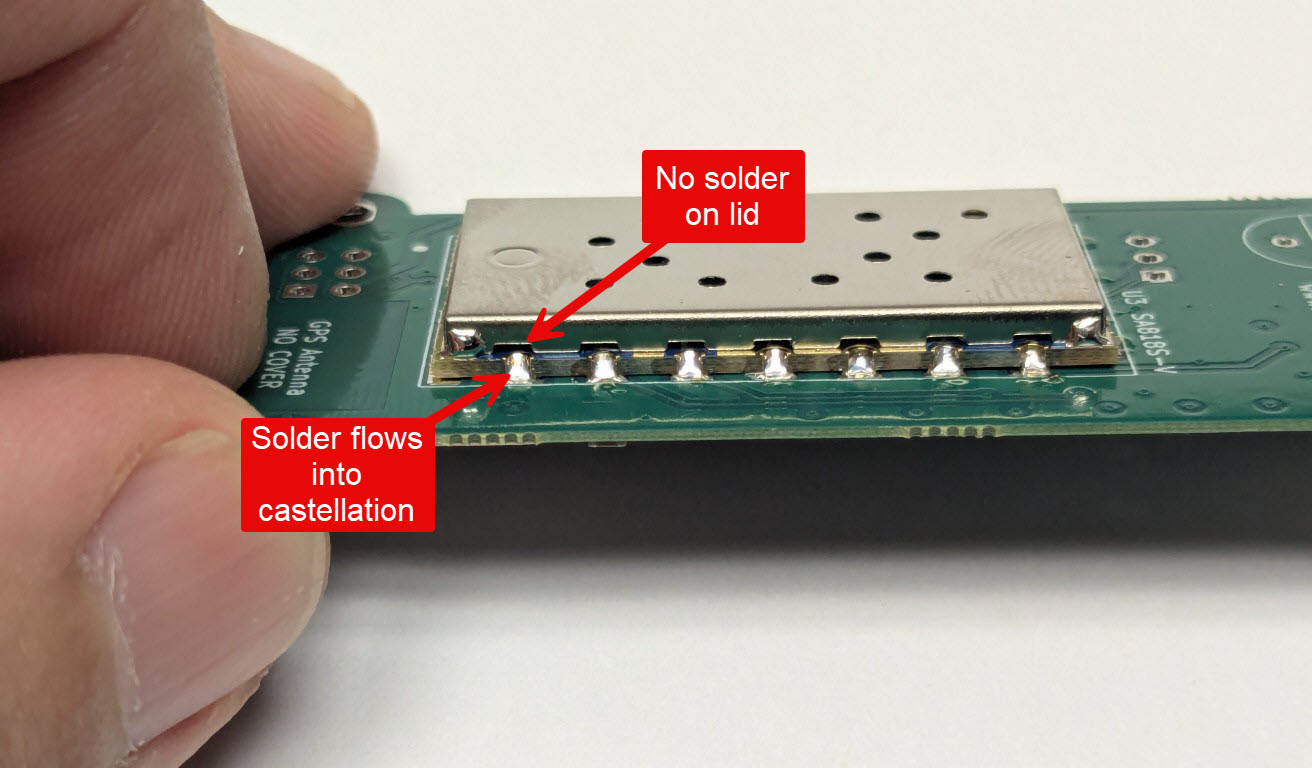
Inspect each pad to ensure that solder flowed nicely between the PCB and the edge of the castellation. Be sure that the solder did not extend past the castellation and onto the metal lid.
Programming Header(s)
Before operation, the ptFlex will need to be configured with your callsign and any specific flight parameters desired. The J2 header is used to configure these details once the board is completely assembled.
Install the 1x3 header J2 into the holes near the middle of the PCB. The pins should be installed on the side with all of the SMD components.
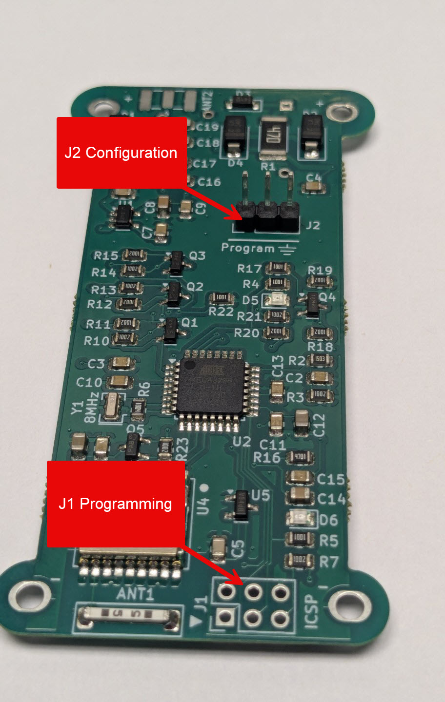
There is a second 6-pin header near the bottom of the board labeled J1. This header is used if you wish to upgrade the firmware that is operating on the ptFlex, and is not required for normal operation.
SMA Connector
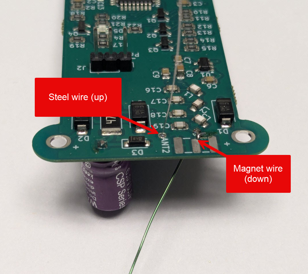
The antenna is connected to the ptFlex tracker through an SMA connector near the top of the board. The SMA can be a snug fit into the PCB. Be careful to not press on the exterior of the SMA jack if it is giving resistance, but instead push directly on the white dialatric inside of the SMA connector. Using a XX" Allen wrench works very well for this purpose.
Piezo Beeper
The ptFlex has an optional piezo beeper that will audibly alert you to certain events on the tracker. This is useful to help ensure that the tracker is receiving a valid GPS lock prior to launching the balloon.
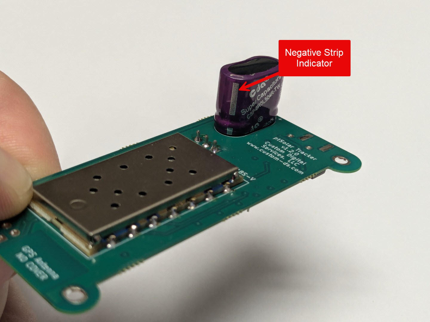
The Piezo is the round device with two pins sticking out of it. It goes into the device labeled PZ1 on the PCB. The device is polarized, so be sure to match up the + on the piezo to the + on the PCB.
Battery Connector
WARNING: This step is the most critcal and dangerous portion of the ptFlex assembly process. Read the instructions, and be sure that you have all of the supplies on hand to complete this step prior to begining.
The LiPo battery (not included) needs to have the connector replaced by the 2.1mm barrel connector (included). The batteries can be sourced for a variety of distributors, including Hobby King.
Once the battery is ready, lay out the barrel connector and cut the leads down to about 3 inches. A somewhat longer lead can be used, but does run the potential of injecting unwanted RFI interference into the ptFlex tracker.
Cut the positive lead, which is the one with the stripe 1cm shorter than the negative lead.
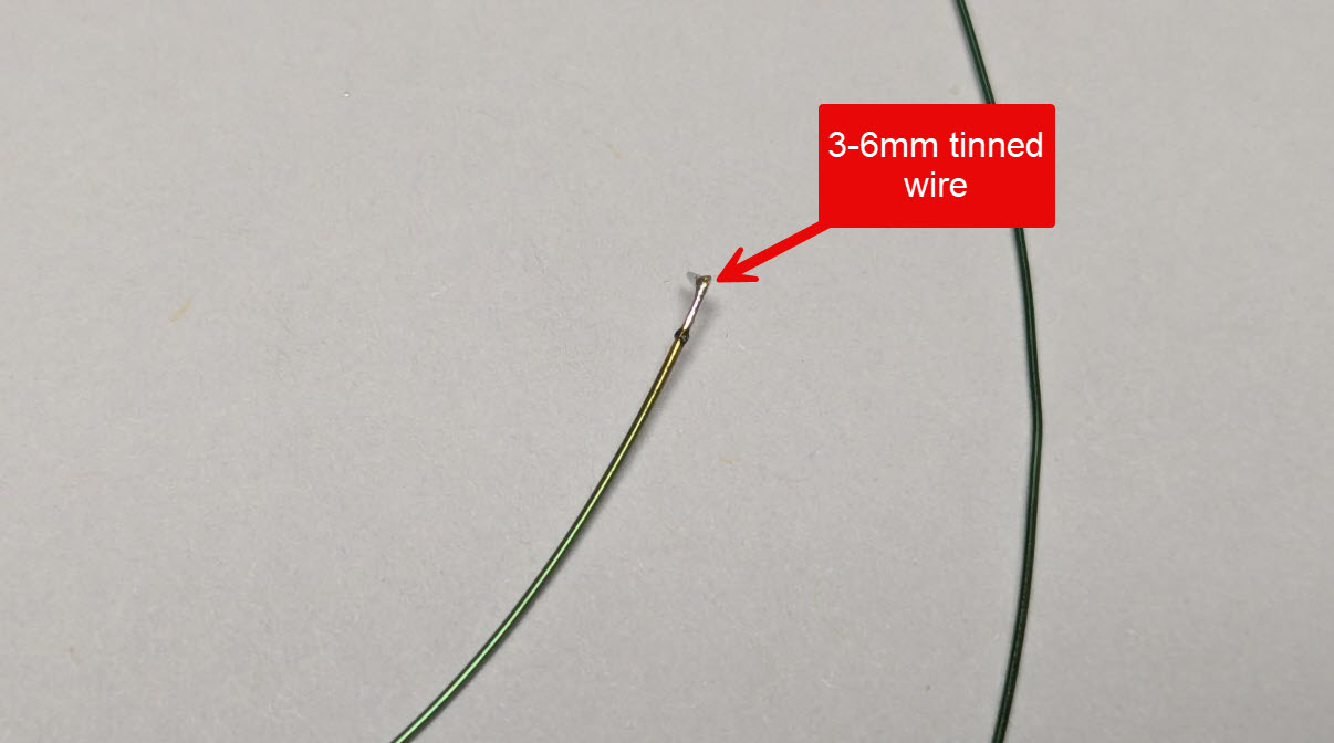
Strip both wires back 5mm, and tin them heavily with solder.
T
d.
Thth.
Insr.
Configuring the ptSolar
Review all of the soldering connections to ensure that they are clean solder joints, and are not shorting out across multiple pads.
The ptFlex needs to be powered up in order to perform the final configuration of your callsign, and any other parameters. Note that this is different from flashing a firmware to the microcontroller, which is generally unnecessary for a purchased kit as the kits already have a default firmware applied.
Applying power to the ptSolar can be accomplished in several ways
- Taking the ptSolar outside in full sun at mid-day
- A 200 watt plant grow light
- Power applied through the J1 6-pin plug, such as with an Atmel ICSP programming cable
Download the ptConfigurator from the ProjectTraveler.org website. ptConfigurator is the software used to set the configuration values on a ptSolar tracker. It will download a .MSI file that can be installed on any Windows 10 or Windows 11 PC. Double-click the .MSI to install the software.
Plug the configuration cable (sold separately) into a USB port. Normally Windows will automatically install the appropriate driver, and create a serial port on the computer.
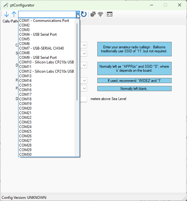
Open the ptConfigurator software on the PC. Across the top toolbar, select the COM serial port from the list od devices.
Helpful Tip: If you are unsure which serial port was created by the Configuration Cable, unplug the cable from the USB port. Click on the round Refresh button next to the list of serial ports. Drop the list of serial ports, making note of which ones have labels next to them such as “COM9 – USB Serial Port”.
Plug the Configuration Cable back into the PC and click the round Refresh button again, looking for a new COM port that previously did not have a label associated with it.
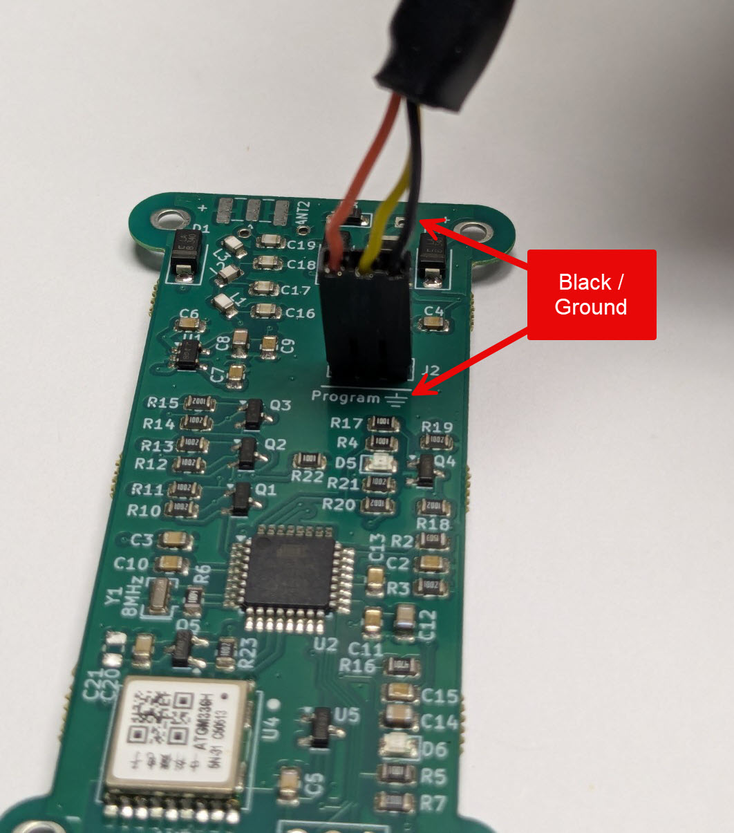
Plug the Configuration cable into the 3-pin J2 plug near the top of the PCB. Align the black ground wire with the ground symbol on the pin closest to the edge of the board.
Configuring the ptFlex
Apply power to the ptSolar tracker through one of the means listed above. If you are outdoors using the sun as your power source, note that it can take 15-60 seconds of full sun before the tracker powers up. You should see the green LED D6 flash as the microcontroller powers up.
Once the tracker is powered, click the Down Arrow button to download the currently running configuration from the Tracker into the ptConfiguration tool. You should see “Config Version: PT0101” at the bottom of the status bar in ptConfigurator. This is your indicator that the configuration was read from the ptSolar.
The most common settings for Pico Balloon tracking are:
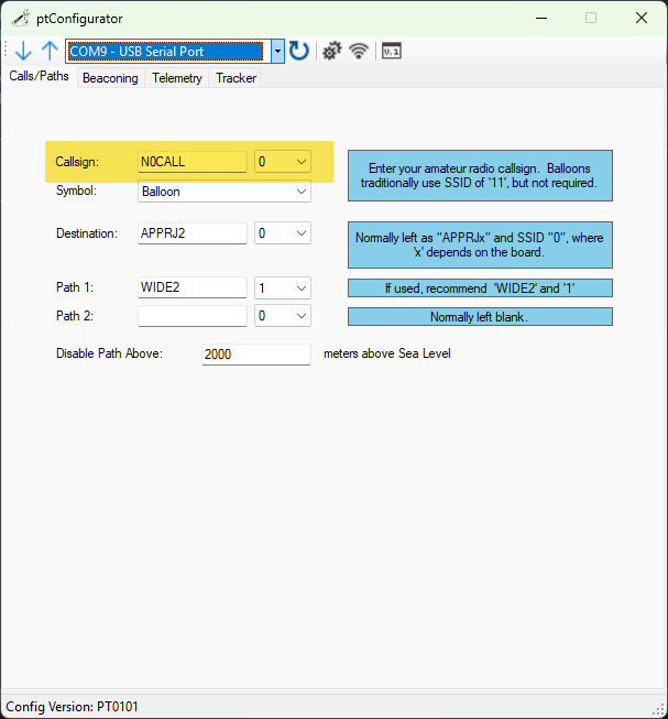
Calls/Paths
- Callsign – Set the callsign with your ham radio callsign. If you wish to use an SSID, select it from the drop-down menu to the right of the Callsign field.
Beaconing
- Low Power Beaconing – This puts the tracker in the low power mode that is optimized for solar operation.
- Minimum delay between transmissions – This is how often it will transmit assuming it has sufficient solar power, and has a solid GPS lock. On the ground this time will often be longer than the value specified, however when the Pico balloon is at altitude, it will generally beacon at the fastest rate specified.
- GPS Voltage Enable Threshold – The voltage that the GPS becomes active. 3500mV is a safe value. Don’t adjust this unless you understand the ramifications of doing so.
- Transmit Voltage Enable Threshold – This voltage that the tracker waits to build up to before transmitting. 4100mV is a safe value. Don’t adjust this unless you understand the ramifications of doing so.
![]()
Telemetry
- Status Message – A free form area that transmits at the end of the packet. A shorter message will consume less power during the transmit cycle. Avoid using punctation unless you’re familiar with the APRS protocol.
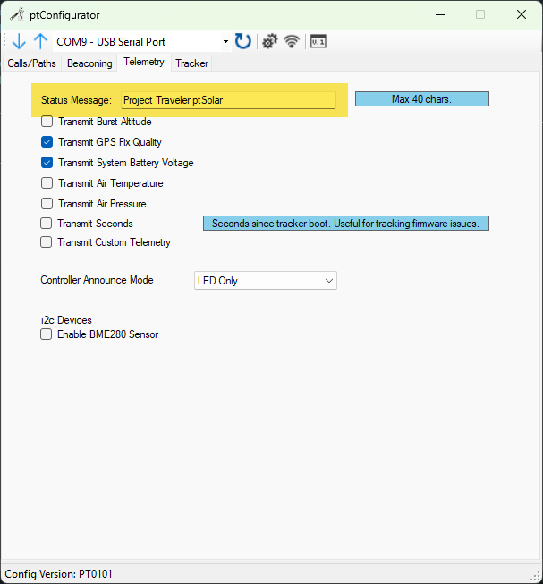
The other check-boxes can usually be left as default.
- Burst Altitude is irrelevant for a Pico (floater) balloon.
- GPS Fix Quality can be useful for watching the status of the GPS receiver.
- Battery Voltage can be useful for monitoring the output of the solar panels.
- The ptSolar does not contain air temperature or pressure sensors, and these options will not work on this tracker.
- Transmit Seconds will transmit the number of seconds since the tracker powered up. This can be useful if you are curious if the tracker is loosing power due to low solar output or another issue.
- Custom Telemtety is supported, but requires a custom firmware build. This is generally not used on a ptSolar.
- The Controller Announce Mode can be set to Off or LED Only. Turning the light off saves a very small amount of energy, but is not noticeable under normal circumstances.
- There is no BME280 sensor installed on the ptSolar tracker, and checking this box will not do anything.
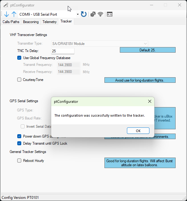
Tracker
- Unless you want your tracker to stay on a specific frequency, check the box to Use Global Frequency Database. This will look up the region’s APRS frequency based on the current position.
- Powering down the GPS during transmission will help avoid the Super Cap from falling below unsafe levels during the APRS transmission.
- Delay Transmit until GPS Lock will delay the transmission past the number of seconds defined on the Beaconing page in order to wait for a valid GPS lock. This can be very useful in low power, and high RF-environments where the GPS may be struggling to get a solid lock.
![]()
Applying the Configuration
Once all four tabs of the ptConfigurator are configured as desired, press the Up Arrow. If the tracker is still powered on, it will upload the settings permanently into the EEPROM on the ptSolar.
Always verify that the settings were properly applied. The best approach is to close out of ptConfigurator, then re-open it and re-select the COM port and click the Down Arrow to read in the configuration from the ptSolar. Your settings should re-appear inside of ptConfigurator.
It is also recommended to take the ptSolar outdoors where it can receive sufficient sunlight and a solid GPS lock, and verify the APRS reception using a local APRS receiver. Note that depending on your proximity to an iGate receiver, it is common for the ptSolar tracker to NOT be gated onto the Internet until it has attained a couple hundred meters of altitude.