Our tracking system of choice has included the Kantronics KPC-3 Terminal Node Controller from day one. These are nice, compact little units that can often be found a hamfests for well under $100, and they just work. Except when they don't.
One of the major drawbacks of these units is that they use the hard-to-find DB-25 connectors, and they require hardware flow control pins to be connected up. It's possible to disable the flow control, but at some point, you have to have a full RS-232 cable that supports flow control in order to disable it. Last minutes changes to tracking stations have frustrated many users because they grab an incompatible serial cable, or forget to configure hardware (RTS/CTS) flow control.
Well, no more for us. The new standard configuration for KPC-3 TNC's includes a built-in FTDI chip to convert USB into the required serial signals. As part of that, I have disabled via hardware the whole flow control problem, so that no longer matters. And as an added bonus, the whole setup now is powered off of the 5V from the serial bus!
Inspired by an article in the November 2014 QST, by David Martin, K5DCM, I decided to take his work a couple of steps further.
What is Needed
- A functioning Kantronics KPC-3. These instructions are NOT valid for the KPC-3+, but probably could be easily adapted.
- Sparkfun FTDI Basic Breakout Board (5V)
- A drill with a 5/32" drill bit.
- Dremel Tool with a milling bit.
- Hot glue gun with glue.
- 47k resistor.
- A few short lengths of wire (about 12cm each).
- A soldering iron and a few basic soldering supplies.
The whole process should take less than an hour and is a fairly easy mod.
Physical Modifications
Begin by disassembling the KPC-3. There are two screws on the sides of the case, two screws on the front of the case, and four hex nuts attached to the DB connectors on the back of the unit. Remove all of these.
On the rear of the chassis, mark a whole 10mm in from the right, and 8mm down from the top of the case. Drill a single 5/32" hole at this location.
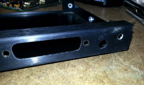
Using the Dremel tool, elongate the hole left and right so that the USB-mini connector slips inside of the newly formed hole.
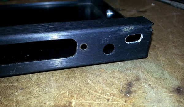
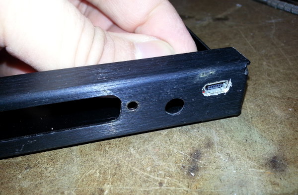
Test-fit the USB jack in the hole, make sure that it fits fully through the hole, and that the Sparkfun PCB board rests securely against the inside of the back chassis.
Preparing the Sparkfun FTDI Basic Module
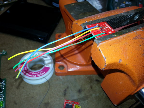
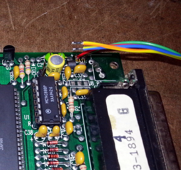
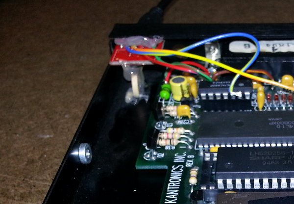
The FTDI module comes with a .1" female header on the back of the PCB, which I removed in favor of a sold, soldered connection. Remove the header from the board, and in its place, solder four wires to the pads of the PCB. The pins are labeled on the opposite side of the FTDI module but be careful while flipping back and forth to read. Only four, 12cm wires need to be connected.
From right to left, as shown in the photo below:
| GND | Electrical Ground | Attached to the green wire. |
| CTS | Clear to Send | Not used. |
| 5V | +5 Volts from USB | Attached to the red wire. |
| TXO | Transmit Data from the PC | Attached to the yellow wire. |
| RXI | Receive Data to the PC | Attached to the blue wire. |
| DTR | Data Terminal Ready | Not used. |
Modifications to the KPC-3 Power Supply
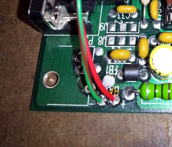
The KPC-3 is designed to be operated at voltages above about 7V DC, so a few modifications need to be made in order to operate it at a flat 5V. Remove the DC power jack from near the back panel, and install a small jumper wire back in across the two holes closest to the DB-25 connector. See photo below.
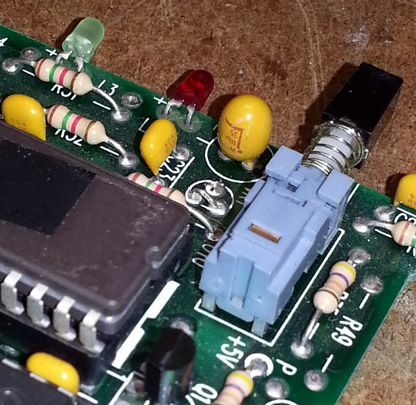
At the front of the KPC-3 near the power switch, there is a small voltage regulator labeled VR1. Remove this regulator and install a small jumper wire across the two pins to the rear of the PCB board. See photo below.
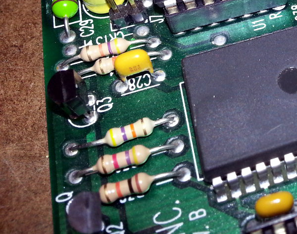
About halfway between the power jack (removed) and the voltage regulator (removed), there is a 150k resistor labeled R40. Remove this resistor, and replace it with a new 47k resistor.
At the rear of the PCB near the power jack that was removed, there are two terminals where a 9V battery can be used to power the TNC. If installed, remove these wires and in their place, insert the 5V and GND wires (red and green in my case) into the + and - holes, respectively.
This concludes the modifications to the power supply circuit. At this point, the KPC-3 is STRICTLY capable of receiving 5V, and any higher voltages will destroy the unit. (Do NOT power up the TNC with a 9V battery.)
Modifications to the RS-232 Circuitry
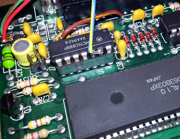
In order to disable the hardware flow control, the RTS (Request to Send) must be wired back into the CTS (Clear to Send) lines. Do this by inserting a short jumper wire between pin 6 of IC U1, and the leg of R44 which is closest to the battery connection.
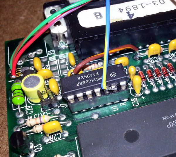
From the Sparkfun FTDI Basic, attach the wire from the RXO (Receive Data) to the pin(s) 12 and/or 13 of IC U1. For me, this was my blue wire. Those pins are tied together on the PCB, so it does not matter if you attach to one or both of those pins.
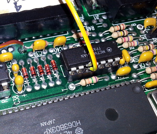
To complete the last connection, remove IC U2 from its socket, and carefully bend pin 10 up and over the top of the IC. This pin will not be used after the modification, but if you are careful, can can preserve the pin so that this modification could be un-done at a later time. While the U2 is still out, carefully attach the TXO (Transmit Data) to the socket's pin 10. This was my yellow wire. Be careful to not melt the socket, and to not smear solder into any of the other socket pins. Re-install the IC U2 into the socket, leaving the IC's pin 10 hanging in the air.
Testing
This would be a good opportunity to test the circuit at this point. Plug a USB mini cable from the Sparkfun FTDI Basic into a computer. The computer should recognize the USB adapter and enumerate a new comm port on the PC.
Next, verify that a green light is lit up on the front panel. The power switch is still functioning, so if necessary, turn on the KPC-3. If you don't get a green light, check voltages along the side of the PCB with the power connections and the voltage regulator. Also, verify that R40 was replaced with a 47k resistor.
Determine which comm port was created, and launch a terminal program on the PC. The default baud rate is 9600, but it could be different on your unit. Turn the KPC-3 off and back on again, and you should see the Kantronics banner come up (unless the TNC was put into KISS mode!).
Type on the keyboard inside of the terminal window, and you should see the characters echo'ed back out to the terminal. If you type 'MYCALL' and press enter, the TNC should report the callsign that it is configured for.
Re-assembly
If all of the testing is finished, plug in the hot glue gun and let it start warming up. Begin re-assembly by sliding the KPC-3 PCB back into the chassis and install the four hex nuts. Slide the front panel back into position and insert the two screws into the front of the panel.
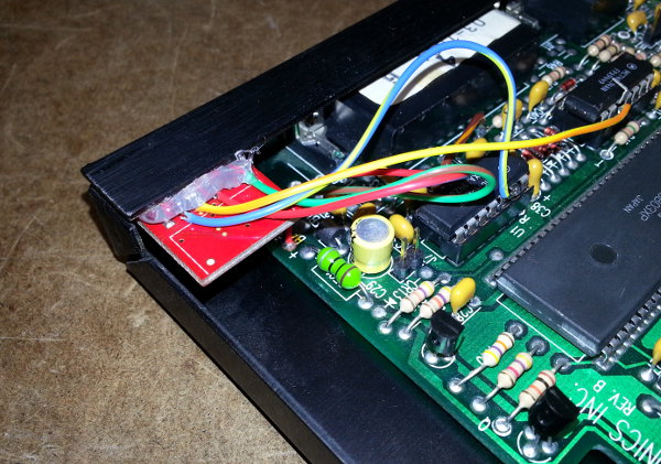
Slip the FTDI Basic module into position and apply a glob of glue along the top of the PCB. I also used a scrap of wood from a Popsicle stick and glued it to the bottom of the chassis to help support the weight of the module and its USB cable.
Finish the re-assembly by putting the top cover on, and replace the final two screws. At this point, your KPC-3 has been converted to USB and is powered by the USB port.