The ArduinoTrack Flight Controller is a stand-alone APRS beaconing system, designed for high altitude ballooning in near-space. The complete system with a lithium-polymer battery capable of operating for over 8 hours, an antenna, and a 3D printed carrier board weighs in at about 250 grams. Project: Traveler has been developing, flying, and refining the board since 2010 and it is now considered stable.
The ArduinoTrack features an Atmel ATMega328p processor programmed in the Arduino IDE, integrated GPS receiver/antenna, an (optional) integrated VHF transmitter module, and sensors for temperature, barometric pressure, and battery voltage. All of the configuration data is stored in EEPROM and can easily be changed by using the ArduinoTrack Configurator tool by anyone with a Windows PC and a TTL serial interface cable.
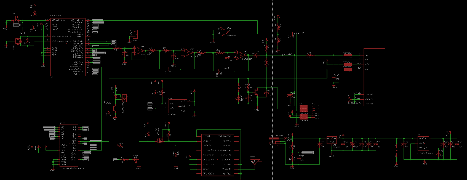
Hardware
The shield hardware is based around an Atmel ATMega328 microcontroller, an MCP6L04T-E/SLCT rail-to-rail op-amp, a Ublox MAX-M8Q GPS module, and optionally a RadioMetrix HX1 VHF transmitter. For details on the hardware, including schematics, PCB's and EagleCad files, visit the ArduinoTrack - Hardware page.
Firmware
The firmware is comprised of three separate Arduino sketches, only one or two of which are required for any particular flight configuration. While regular updates are being made to the firmware, it is not necessary to alter the firmware in most cases to prepare the AruinoTrack for flight.
For details on the hardware, including schematics, PCB's and EagleCad files, visit the ArduinoTrack - Firmware page.
Configurator Software
The ArduinoTrack Configurator is the final piece used to configure the settings which are stored in non-volatile EEPROM. Download and install the Configurator on your Windows PC. When complete, launch the Configurator.
From the dropdown at the top of the window, select the Comm port that the Arduino controller is connected to (this would either be the standard Arduino Uno/etc. or the combined ArduinoTrack Shield if you are using the Combined firmware. If you are using the Combined shield, then you will need to use a 5V TTL adapter cable and feed the serial data into the three-pin header located between the Atmel and the piezo element.
Once the port is selected, press the blue download button and immediately press the reset button on the Arduino. If successful, the current configuration that is install in eeprom will be shown in the Configurator tabs. You can now adjust these settings as necessary. When finished, press the red Upload button to write the configuration back to the Arduino.