Project: Traveler has built and tested a variety of ATV antennas for balloon use, for both on the ground and in the air. By far, the most sucessful balloon antenna that we have come up with is the "Little Wheel", which is a scaled down version of the "Big Wheel" that appeared in a magazine article many years ago. In essence, the Little Wheel is an omni-directional, horizontally polarized antenna with a small amount of gain.
The decision to go with the Little Wheel came after a couple of flights under our belt of watching the capsule, camera, and therefore, antenna, spinning in circles. Because of all of this spinning, all of the antennas that were tried produced a noticable amount of signal fade as the package rotates. Even a dipole mounted vertically had a significant amount of fade in it because the coax feed, nearby metal objects, etc tend to distort the clean antenna radiation patterns found in the books.
We flew our first Little Wheel antenna in 2002 on our PT 2002b flight, and had far superior performance to anything we had tried, however we found that the design tended to be fragile, especially when you dropped a fully loaded 5+ pound box on it. Over the course of the next year or so, we came up with a complete redesign of the entire system that gave us flexibility and integrity throughout the flight.
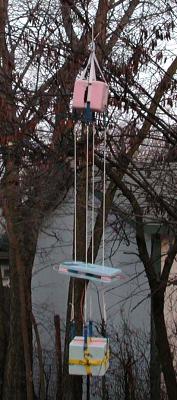
The capsule stack shown includes our primary APRS package on top, with four nylon load-lines which support the bottom capsule. Inside the bottom capsule is a totally independent battery, controller, GPS, and ATV camera/transmitter. Suspended in between the two capsules is the Little Wheel antenna. The antenna is built (permanently) into a 1/2 inch styrofoam sandwich that protects the delicate components and solder connections from the turbulance and impacts of flight. Good quality, Teflon RG-58 coax is used to connect the capsule with the antenna.
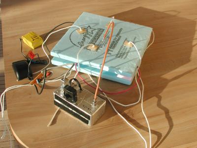
Above you can see the three legs of the antenna sitting on top of the bottom side of the sandwich (see the Antenna Details below). Blocks of Styrofoam were glued to this bottom piece in such a way to support the elements of the antenna so that they could not move. The top half of the sandwich was then epoxied onto those standoffs. Below is the finished product. The silver box is the ATV overlay board and transmitter. The yellow block is the NiMH battery pack.
Antenna Construction
Just a word of caution: I writing most of this off the top of my head. Many of the details for the antenna are sketchy and difficult to find, but this should be pretty close.
In a nutshell, the Little Wheel antenna consists of three fullwave loops that are connected in parallel. All three loops are connected to a central hub which serves as a feed point as well as an impedance matcher.
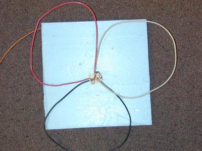
The first pictures shows what the completed antenna should look like - at least before final tweaking and tuning. The general shape should be a circle, and each leg should be symetrical (this picture was taken before the shape was cleaned up). The second picture shows how each leg is connected in parallel to the next. Each loop is connected from the shield of the coax to the center conductor, at approximately 120 degrees spacing.
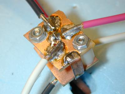
Begin by assembling the feed point. I used two small pieces of unetched circuit board that were bolted together with 1/2 inch spacers between them (see below). Size isn't critical, but should be as small as possible. The spacing between the plates should be as close to .5 inches as possible. I used a Dremel tool to cut away some of the copper plating from around the bolts so that the two plates are electrically isolated.
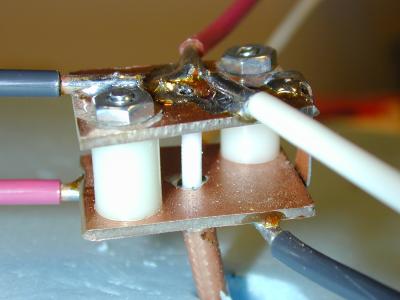
Next I drilled a couple of holes through the middle of the plates and fished a piece of Teflon coax through. The coax braid was fanned out and soldered to the bottom plate, and the center conductor/dialectric is fed up and is soldered to the top plate. This step is probably the most critical to building a strong antenna that can withstand being whipped around and frozen down to -50C.
Once the feed is installed, it's time to build the elements. I used some solid copper wire that I recovered from some old Romex house wiring (12 or 14ga). Each element should be one wavelength at the desired frequency of operation, in my case (434MHz), about 69cm. I stripped back about 1cm of insulation and soldered each loop to both the top and bottom plates. It's quite tricky to get a good solder joint, especially without loosening the joint next to where you are working, so plan on taking your time on this.
The last step is a matching stub. I used a small strip of copper that is soldered directly between the top and bottom plates. This can barely be seen in the above picture at the right side of the picture, near the white wire. This wire effectively matches the input impedance to 50 ohms for low SWR's.
Antenna Tuning
Tuning is very simple with this antenna. If everything is built correctly, it should tune up initially to somewhere less than about 2.5. To bring the SWR down to around 1.1, simply adjust the spacing between the elements. This is just a trial-and-error procedure, and is best done with a device such as and MFJ Antenna Analyzer. The nice thing about building the antenna into the Styrofoam is that once the antenna is tuned, you glue a few blocks of Styrofoam around the elements to keep them in place.
The antenna should have a fairly broad bandwidth, covering 5-10MHz at less than 2.0. In the several prototypes that we have built, we haven't had any problems with tuning