I finally traded in the mini-van for something a little more fun. The one thing that I was very scared of was the space (or lack thereof) in the Jeep compared to the older Grand Caravan that I used to drive. I had custom built a center console on the Caravan, and it could hold practically as many radios as I could afford. The Jeep, on the other hand, was another story.
I reluctantly decided to nix the idea of putting HF in this vehicle. I've found that I just don't use it that often, I didn't have room for the radio, and I especially didn't have room to store several Ham Stick HF antennas in the back (like I did in the Caravan). So that left me with a much more manageable problem of where to put my Alinco DR-620 dual band rig, which fortunately for me, included a detachable/remotable face.
In my Grand Cherokee, I decided to mount the radio's head in what used to be a small cubby hole in the front dash. Once I had decided where to mount the head, I started the install by getting through the firewall.
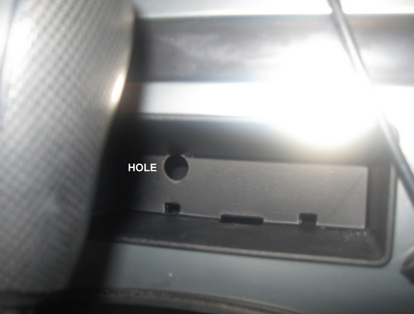
I pulled the plate from the under side of the dash (just under the steering wheel) and started looking for a clear area. In the past, I've had some luck at utilizing an existing grommet that had been placed, but not used - presumable it was for a feature that didn't come with my make/model. There was no such luck this time, and I wound up drilling. The best spot that I could find due to the brake's master cylinder and associated plumbing was just under the accelerator feed.
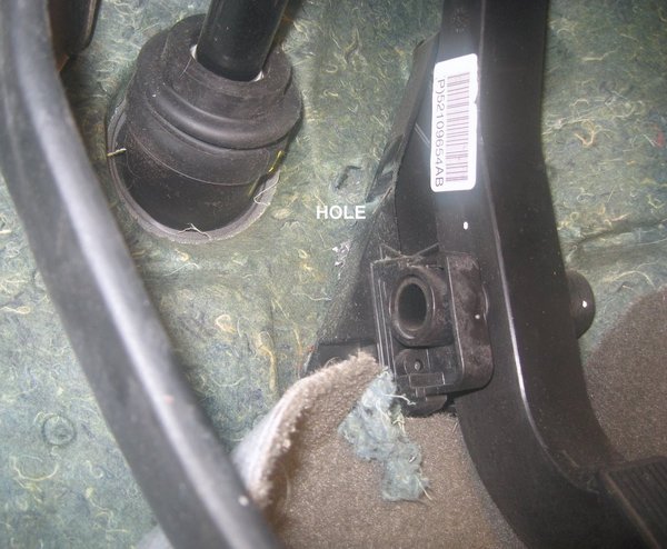
The round thing on the left is the steering column, and the bar on the right, is the accelerator pedal.
Here you can see the hole from the engine side. The hole is right in the middle of the photo.
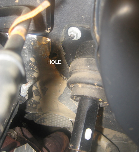
I decided to use my lip-mount dual band antenna that I already owned to mount on the hood of the Cherokee. Through the hole, I ran both the power and an RG-142 teflon coax between the passenger compartment and the engine compartment. Using tie-wraps, I kept the cables tied in position to reduce vibration stresses and failures.
The power cable is a molded (zip style) 14 gauge power cord purchased from PowerWerx.com. Although technically the ground could be picked up through the chassis at the radio, and you'd only have to run a power cable, that is not a good idea.
By running the pair all the way back to the battery, you minimize your radiated EMI because of the close spacing between the conductors - I've found this to be very critical on modern computerized vehicles.
Once I had the cables in the engine compartment, I went back inside and started fishing them through the interior. The drivers side seat is electrically powered, but there was still enough room at the front to mount the body of the radio under it. Routing the power and coax actually turned out to be one of the easier tasks - I just lifted up the edge of the center console and slipped them up under the plastic. I had already taken the cover off of the gear selector, so I was reasonably confident that there wasn't any critical or sensitive wiring under there.
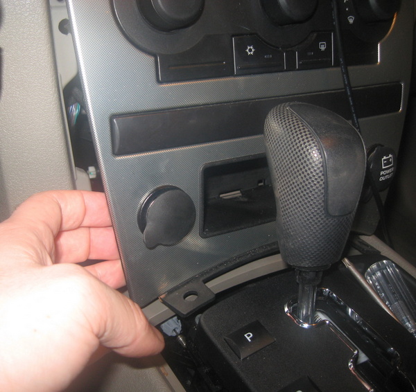
The most difficult part was getting the console apart far enough to route my cable from Alinco's separation kit. To do this, I took the gear shifter covers apart, and then pulled the front console's plate back away from the console.
I drilled a 1/2 inch hole in the top side of the cubby hole. This is where the separation cable is routed.
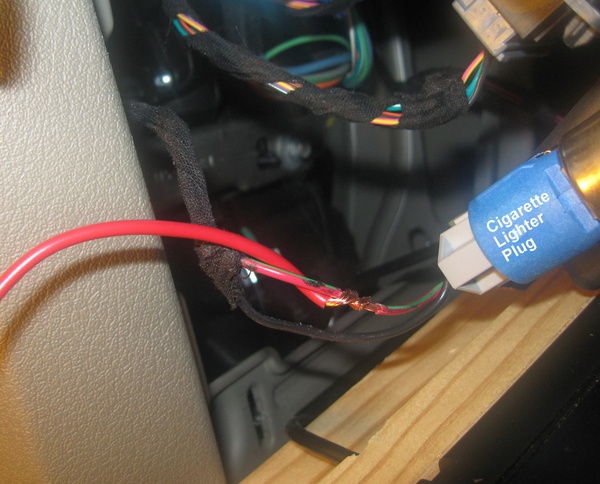
While I was in here, I picked up +12V from the switched cigarette lighter plug. I don't actually pull any significant current from this plug, but instead I use it to drive a relay. That way I can switch off all of my radios (which are powered directly from the batter), any time the ignition key is switched off. I wrote up my wiring concept years ago and can be found on the RCKARA website. Note, I no longer use the "Accessory Line (from stereo)" as the schematics point out - instead I use this cigarette lighter power.
My five year old daughter started helping me at about this point. A smile means things are starting to come together...
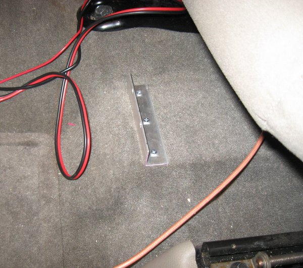
Under the seat, I screwed a piece of aluminum angle directly into the floor, which happened to be a flat plastic vent.
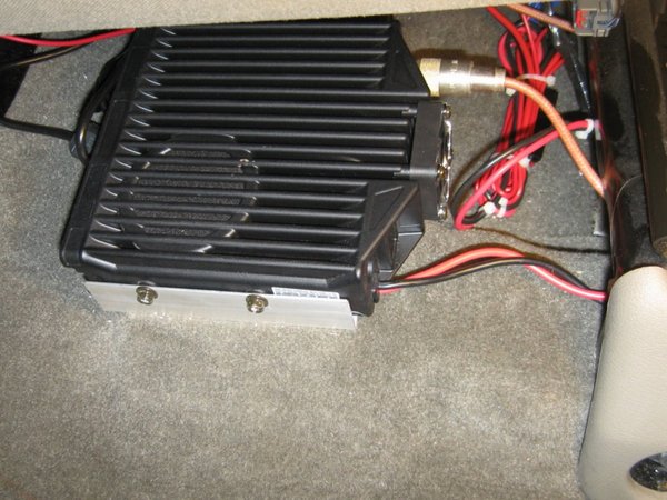
The radio rests on the floor under the drivers seat, with the speaker pointed up. There is more than enough audio in this configuration.
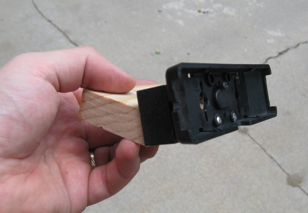
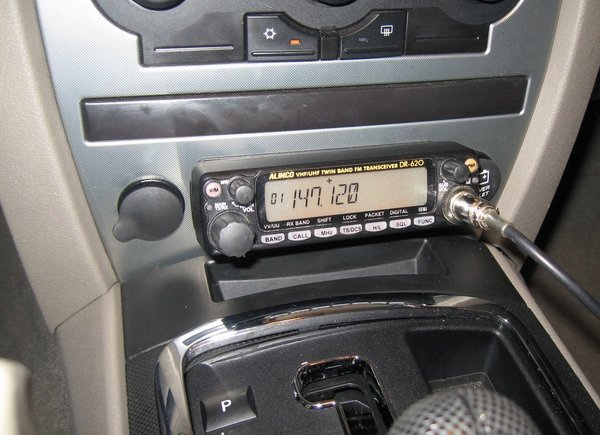
The face of the radio is mounted to a couple of blocks of wood, by using the mounting bracket that is supplied as part of the separation kit. I cut two blocks of wood, and painted the forward one black for fear that you might have been able to see it sticking out from behind the radio face. The rear block was beveled up at 25 degrees inclination to make the screen easier to read while driving. I screwed the two blocks together with a pair of counter-sunk screws, then attached the included Alinco mounting bracket to the front wood piece using a couple more screws.
I drilled a hold big enough to pass the RJ-11 connector for the separation cable through the bracket, and after some trial-fitting and trimming, I was ready to install the mounting bracket.
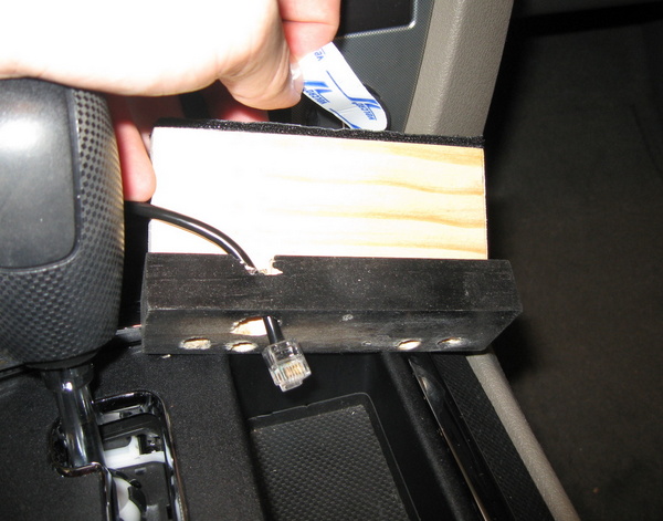
All that was needed was some heavy-duty Velcro fastener. The Heavy Duty stuff that you can find at the hardware store works wonders - just expect to pay $3-$4 per foot for the stuff. Anything cheaper will come loose, so don't waste your time. I put a light coat of polyurethane on the back edge of the rear wood block to help the sticky Velro stick better.
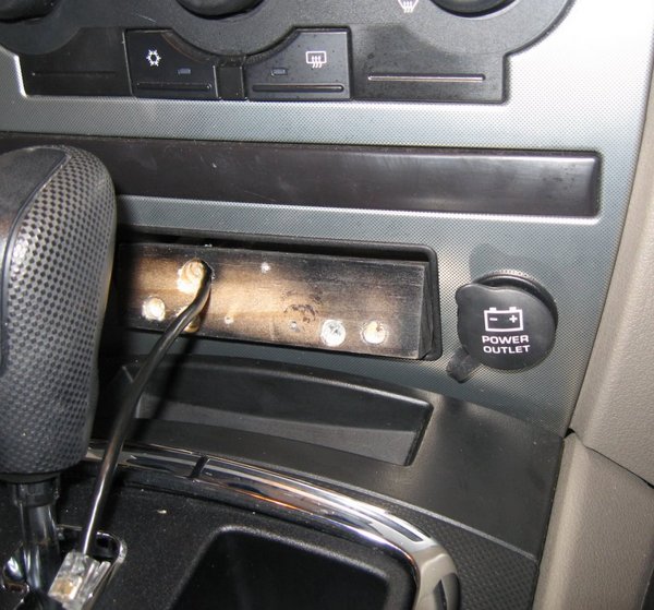
Here's the wood mounting bracket installed in the cubby hole, and ready to have the plastic bracket installed for final assembly.
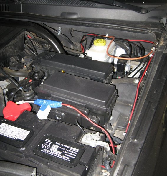
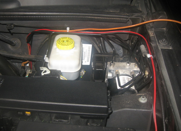
Once all of the cables inside the vehicle were terminated and secured, it was time to go back into the engine compartment to attach the antenna, and put the circuit breaker in at the battery. Here you can see the 15A breaker sitting on top of the battery, and the black negative lead attached directly to the negative post.
Now it's time for the smoke test! No smoke this time. The install looks good and clean, and I haven't noticed any EMI-related quirks when transmitting.
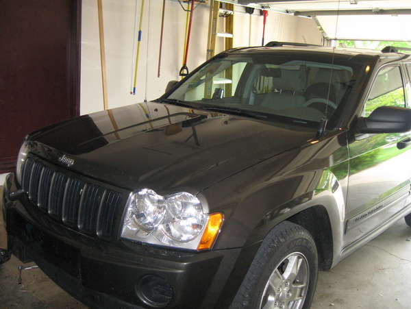
Here's the completed installation, ready for our first road trip. The dual-band antenna is the one on the right (drivers side).