The ptConfigurator tool is the Windows application that is required to be installed on a PC, running Windows Vista or higher. The ptConfigurator requires Microsoft .Net 4.5 to be installed for operation.
Install the ptConfigurator software by downloading it from Project: Traveler’s website. The download is a .MSI installer package that will install itself on a Windows PC with just a couple of clicks.
To configure a ptFlex flight controller, a 5V-TTL level adapter must be used, such as the FTDI cable available from Custom Digital Services. Connect your TTL interface cable and if necessary, install any drivers from the manufacturer.
Connect the ptFlex to the cable, and then launch the ptConfigurator program from the Windows Start Menu.
With the program open, select the Comm Port that is appropriate for your particular programmer/configuration. Click the blue Down Arrow and apply power to the ptFlex to download the current configuration from the flight controller. Note, if the ptFlex is already powered up you can also press the Reset button to reboot the unit at this time.
Once the configuration is loaded, you should see the Config Version at the bottom in the status bar change to something other than “UNKNOWN”. The current configuration version for the ptFlex flight controller is PT0003.
At this point, you will be ready to make the configuration adjustments as necessary for your particular mission.
Calls/Paths
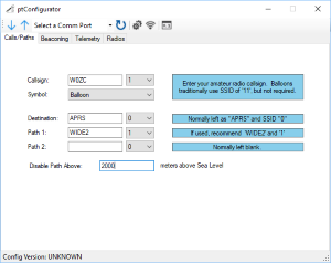 The Callsign of the ptFlex is the most important piece of information to be entered in the first tab. The callsign should be the alpha-numeric amateur radio callsign of the group or individual responsible for the flight controller. For operaion, it is required for the individual to be a licensed amateur radio operator, of at least a Technician Class License (in the U.S.) to legally operate the tracker.
In addition to the callsign, the SSID field (the numeric drop-down to the right of the callsign) should be specified. This value is not critical, but should be unique if there are multiple trackers being used on this callsign.
The Symbol is a list of optional APRS icons that will be presented by the ptFlex. For High Altitude Ballooning, the Balloon Symbol is normal, but not required.
The Destination can generally be left as APRS and (0).
The Path1 can generally be left as WIDE2 and (1), and the Path2 can be left blank and (0) for most High Altitude Ballooning operations. If you are operating a ground-based beacon, you may need to adjust these parameters depending on your local APRS network. For more information about how Paths, Digipeaters, and iGates work together to track the ArduinoTrack, see the FAQ: Why doesn't my tracker show up on the Internet.
If you are operating the ptFlex onboard a balloon or other aircraft, it is generally considered polite to disable the Path above a certain altitude. This value is in meters above mean sea level, and it is usually safe to disable at an altitude above 1,500 meters above the average terrain. For example, if the ground elevation in the expect flight area is 500m MSL, then enter 2000 into the Disable Path Above field.
Beaconing
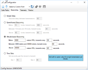 There are four beaconing modes of operation to choose from.
Simple Delay
The Simple Delay is a count-down timer that sends a packet, and then waits X seconds before sending the next packet. Because of the time needed to actually send the packet over the radio, a delay of 60 seconds will NOT result in exactly one packet being sent every minute. Instead, a packet will be sent out about every 61-62 seconds, and may vary slightly depending on several factors.
Speed-based Beaconing
Speed-based beaconing can be useful when tracking an automobile. When an automobile is sitting still (i.e. parked) there is no need to beacon any more frequently than every 5-10 minutes (300-600 seconds). Alternatively when a vehicle is moving relatively slow, it can be assumed that they are traveling around inside of a city, and likely to make course changes on a regular basis. Therefore beacons every 30-120 seconds may be appropriate for maximum resolution. On the highway, beacon rates can safely be reduced to 120-300 seconds as major course changes are less likely.
Altitude-based Beaconing
Altitude-based beaconing is often used for High Altitude Ballooning, where it may be desirable to have high beacon rates for the balloon position as the balloon is in the final decent phases of the flight, however, during the bulk of the flight (typically altitudes between 5000m and 25,000m MSL) the packet rate can be reduced to avoid traffic congestion on the radio channel. As the balloon nears the burst altitude, it may be desirable to increase the packet rate again so that a burst condition is identified as quickly as possible.
For High Altitude Balloons, packet rates of 30-45 seconds below 5000m, 60 seconds between 5,000m and 25,000m, and 30-45 seconds above 25,000m are generally acceptable.
Time Slots
The final beaconing option is Time Slots, and this is sometimes used when a large number of becaons will be used in close proximity to each other. In this mode, the ArduinoTrack will wait until the specified number of seconds past the minute (per the GPS’s clock), and will transmit a single packet out at that time. You can set either one or two slots per minute (e.g. 15 and 45 seconds past the minute). If you only want the ArduinoTrack to transmit once per minute, enter the same value into both Slot1 and Slot2.
Telemetry
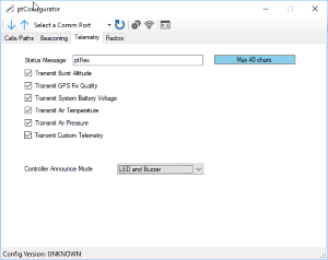 The Status Message is a free form field available to announce the owner of the balloon flight. Generally speaking, it is best to avoid any special punctuation, and stick to just letters, numbers, and spaces.
Transmit Burst Altitude will track the maximum altitude observed on the GPS of a High Altitude Balloon and will transmit that peek back as part of the status message throughout the descent. This is the most accurate method to know the actual burst altitude of your balloon.
Transmit GPS Fix Quality will transmit how many satellites are being tracked by the GPS, and whether or not you have a 3D fix.
Transmit System Battery Voltage will indicate in volts what the charge on the battery is.
Transmit Air Temperature will transmit the Inside Air Temp (IAT) observed by the BMP280 sensor on the ptFlex circuit board. This value is in Celsius units.
Transmit Air Pressure will send the air pressure detected by the BMP280 sensor.
If the custom.h/custom.c firmware has been modified to support other sensors on the I2C bus, then this checkbox will cause that code to be executed. If you want to eliminate that code from executing via configuration, you can uncheck this box.
The Controller Announce Mode indicated whether to give status annunciations via the green status LED, the piezo buzzer, both, or neither. For High Altitude Balloon launches it is generally recommended to run in Both mode, as important status conditions can be audibly heard during the launch process by the piezo. However, during the testing and integration process, it is sometimes preferred to leave the piezo turned off as it can be annoying. For definitions of the status messages, see the section Understanding the Status Annunciations.
Radios
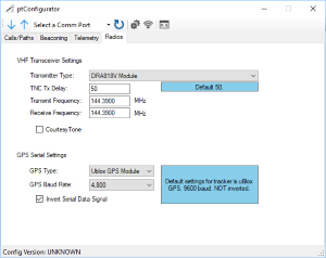 The Radios tab is broken into two general sections: the VHF Transmitter and the GPS receiver.
VHF Transmitter
If the DRA818V Module is selected and the pfFlex board being configured has the DRA module installed, then the frequency of the transmitter can be configured via the Transmit Frequency and Receive Frequency boxes below.
If the Standard Transmitter option is selected, those frequency values will be ignored.
GPS Receiver
Unless you are implementing a custom circuit into the ptFlex firmware, the GPS Serial settings should not be chaned. Their defaults are "Ublox", "4,800 baud", and "Invert Serial Data".